
Recently I recycled some old mobiles phones I had. There was a Nokia 5800 (This ONE). I decided to remove the touch screen sensor and play around with it. So, I dismantled the phone ad remover the touch surface.
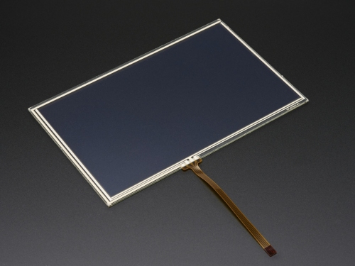
The specific touch screen is a resistive touchscreen. It is composed of two surfaces, with specific resistance, really close together. When pressure is applied, the two resistive surfaces contact each other and create a specific resistor network. When applying voltage to this network it creates an output voltage that is related to the position of the contact. Measuring this voltage, someone can find the coordinates of the touch. This could be easily implemented using a microcontroller. With an Arduino and ATmega328p for example.
There are various types of resistive touch surfaces. The most common one is the one with for wires. Like the one I removed from the phone. The way to calculate the position of the touch is independent of the surface size. Every wire pair of such a surface, when no pressure is applied, has a constant resistance value. My surface has a pair with a resistance of 875 Ohm (horizontally as shown in the picture bellow) and 305 Ohms to the other one (vertically as shown in the picture bellow).


The logic for finding the coordinates is quite simple. For X axis… We connect the wires of the X axis (the ones with the 875 Ohm resistance) between 5 volts and a ground (to a logic high and a logic low I/O pins of the mcu). The other pair (Which we now refer as the Y axis) we leave the one floating (to a High-Z pin of the mcu) and measure the voltage to the other one (connect it to a channel of the ADC of the mcu).
It’s really a potentiometer. By measuring the output voltage of the potentiometer (for the two end positions will be 0 to 5 volts), we can extract a result for the position o the wiper. If for example the ADC reports a voltage of 2,5 volts we know that the wiper is in the middle of the X axis.


It is exactly the same for the Y axis. We connect the wire of the Y axis Υ (the ones with the 305 Ohm resistance) between ground and 5 volts (to a logic high and a logic low I/O pins of the mcu). The other pair, we leave the one floating (to a High-Z pin of the mcu) and measure the voltage to the other one (connect it to a channel of the ADC of the mcu).


The voltage measured by the ADC has a relation with the maximum value of the ADC (for a 10 bit ADC it will be ADCMAX=1024), the ADC reference voltage (Vref, same as Vcc in our case) and the current value of the ADC register (ADCX). From the way a potentiometer works, we know that the voltage measured by the ADC is proportional of the current wiper position (X) and the length of the potentiometer (XLength). Using those two relations we can calculate the current X position of the touch event (same goes for the Y axis).

In such a surface (with four wires) we can calculate the if there is a touch event present. We can acquire informations for the Z axis. When pressure is applied to point of the surface, a resistance is crated to that point. The value of the resistance is somewhat related to the amount of the applied pressure. If we calculate this contact resistance when can decide if there is pressure applied to the surface.

To calculate this resistance (call it RTouch) we do the following process. We connect the one wire of the X axis to ground and the other to an ADC channel. The one wire of the Y axis to Vcc and the other to an ADC channel. We sample the two ADC channels. We now know the voltage across Rtouch .
If we call the four wires Xa, Xb and Ya, Yb then we must impement the following connection in order to measure RTouch.

For the voltage across RTouch (Z1 and Z2 points voltage), By using the equation for the output of a voltage divider and the voltage reported by an ADC we have the following relations.
When measuring the position of the X axis, we really implement the circuit bellow
Using again the equations for a voltage divider and the voltage measured by an ADC we arrive to the following result.
Using the above equations and solving for RTouch, we have the following equation. Where RTotal is the total X axis resistance (875 Ohm), ADCMAX is the max value of the ADC (for ATmega328p 1024, 210), ADCX is the value of the ADC register while calculating the X axis position, and ADCZ1, ADCZ2 is the ADC register values while measuring across RTouch (click HERE for a detailed analysis).
For every measurement, if there is any pressure present, the for wires (Xa, Xb, Ya, Yb) must be connected the way shown to the table bellow.
As we can see Xb and Yb wires will always be in a state of logic low (GND) or logic high (Vcc) or high impedance input (High-Z). We can conect those two in any GPIO of our microcontroller (eg. Xb to PB0 and Yb to PB1). Xa and Ya can be connected to two of the ADC’s channels (eg. Xa to PC0 and Ya to PC1).
To be continued…
