
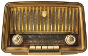
In my everyday life I listen to the radio a lot. Some days ago, my home FM receiver din;t want to cooperate with me. It would turn on or off by it self, change the station etc. Most probably a switch contact must be dirty. I decided to take it apart and thoroughly clean it. When I tried to unscrew it, I saw that it is using safety screw and it needs a 20+ centimeter (8+ inches) screw driver. It seemed easier to me to design and make a new FM radio receiver, than go search and buy an appropriate screw driver…
I opened my drawer with the various parts from home appliances and found two digitally controlled tuners. One it was from an old TV and FM PC card, from Philips (controlled via I2C bus), and one tuner from and old home HI-FI receiver, with no markings. I decided to use the second one. The presence of TV signal to the first, discouraged me a bit.


Upon taking apart the tuner, I saw it uses two Sanyo (now ON Semi) integrated circuits. To LC72131M witch is PLL Frequency Synthesizer and the LA1837M, witch is a single chip AM/FM tuner ic. LC72131 in order to communicate with it environment, uses a Sanyo SPI like bus. Sanyo calls it CCB (Computer Control Bus). Since it resembles to an SPI bus it is really simple to be implemented in software (Bit Banging).
The problem was that the tuner was completely anonymous. No markings no nothing. It uses a 15 pin header connector, without any infos on the pins. I grubbed my multimeter and started reverse engineering the pins. After some minutes (with the help of the integrated circuits datasheet) I knew what every pin’s function is. After that it came to me the model of the HI-FI I had removed the tuner, found its schematic diagram over the internets, and confirmed my findings.

I grubbed an AVR development board (Arduino UNO), witch utilizes an ATmega328p micro (it is an overkill for this project), a 16×2 liquid crystal display and started building the circuit. I an hour or so, I had started writing the code (in plain C) in Code::Blocks. In the afternoon I had a working code capable of sending commands to the tuner and tune it in stations. Next day I had a fully functional FM radio receiver with a display for the frequency, Stereo mode, and PLL tune indicator. It is controlled by three dip switches. Two for increasing and decreasing the frequency and one for manual or automatic tuning.

All the files (photos, datasheets, schematic, code) for this project are available on my GitHub page HERE. For this implementation I have not enabled the AM capabilities of the synthesizer and the tuner, as I don;t care for AM stations. It is fairly easy though for someone to enable it. The code is well documented.
I might continue adding features. Memory storing for my favorite stations, IR control etc.

Absolutely amazing! Ingenious idea.
Although I’m not at all skilled in electronics (I know only the very basics of it), I would love to give a try. I have 1-2 radio-tuners in my trash box. Hopefully, I’ll take some time for it in the near future. 🙂
Keep in touch.
How did you flash arduino. Found your project. But I did not understand what program you used during development. And if you can podstkazhite which of the project files is firmware. Sincerely.
This is the firmware file https://github.com/firew4lker/AVR_Radio/blob/master/Firmware/bin/Release/AVR_Radio.hex
The software for the development is this: http://www.codeblocks.org/
Hi…
Can I using arduino nano for this project?
Yes, you can.
Thanks…
I have this tuner from Aiwa mini compo. I am still confused about how to move from FM to AM.
one more, can I add a mp3 player chip, how to make the song that is currently playing displaying on the screen.
sorry to ask a lot….i am still analog mind, newbie in digital.
I need some help. I’ve tried this with four different tuner and none work. Please help.
Is the tuners you are using compatible with the LC72131M ?
They all contain LC72131 and LA1823. Im using the Arduino Mega 2560 and Arduino IDE 1.8.5.
You must adapt and recompile for Mega 2560, or use an arduino nano.
thank you for this project. first of all i am sorry for my questions….can i use arduino ide to upload the file? arduino ide can take .ino file, but i dont find it in your program …there is a file called ” main.c” is that the file? OR there is two .hex files inside bin folder, .hex file can be uploaded using xloader to arduino uno…… how do i upload the file to arduino uno..help.
Use this file:
https://github.com/firew4lker/AVR_Radio/raw/master/Firmware/bin/Release/AVR_Radio.hex
I use avrdude to upload my code. As the Arduino IDE does.
thanks for sharing
I have several tuners, about 10 units,
I downloaded the file, and it has been simulated on proteus
and I want to activate the AM band,
can you provide the code to activate it?
thank you for your help, regards
Have a look bellow.
https://github.com/RodLophus/SanyoCCB/
I mean, change it in the code::blocks
Hi sir, I also tried to revive my old tuner, it seems like yours but it had 9 pins, it uses lc7231, and for the tuner, i cant figure out, the marking is removed, its 24 pin smd.
And theres only 1 ic at the back (yours is 2)
Is there any way i can revive it?
Thanks
I really can’t tell without having the tuner. Post some links some high resolution photos off all the components.
Hello Alex. Looking for information about my freshly extracted tuner from a car radio, I found this post. Basically I have something similar, but there are other pins, other circuits and they are separate, but they do the same things. I restarted the module, but in the analog version (it works, but it is very unstable at temperature variations). I have some knowledge in electronics, but less in programming. For me the synthesizer is lc72146. I compared the data sheets and they look identical at first glance. The question is: can I use the code you wrote for the lc72146 circuit?
Only the top left module is mine:
https://vrtp.ru/index.php?s=4ea9906aaba930220a3f94f4195e7b09&act=Attach&type=post&id=328714
The synthesizer:
https://pdf1.alldatasheet.com/datasheet-pdf/view/40781/SANYO/LC72146.html
The project that initially inspired me but I already have an LCD and an arduino nano:
https://radiokot.ru/lab/controller/43/
Unfortunately I can’t attach pictures … P.S. I don’t know Russian but I managed with google translation 🙂
Thank you!
Hello Alex,
Looking for information about my freshly extracted tuner from a car radio, I found this post. Basically I have something similar, but there are other pins, other circuits and they are separate, but they do the same things. I restarted the module, but in the analog version (it works, but it is very unstable at temperature variations). I have some knowledge in electronics, but less in programming. For me the synthesizer is lc72146. I compared the data sheets and they look identical at first glance. The question is: can I use the code you wrote for the lc72146 circuit?
Only the top left module is mine:
https://vrtp.ru/index.php?s=d720211256c152541e534ff3c5aa0247&act=Attach&type=post&id=328714
The synthesizer:
https://pdf1.alldatasheet.com/datasheet-pdf/view/40781/SANYO/LC72146.html
The project that initially inspired me but I already have an LCD and an arduino nano:
https://radiokot.ru/lab/controller/43/
Unfortunately I can’t attach pictures … P.S. I don’t know Russian but I managed with google translation 🙂
Hello. I can;t really answer you. You must compare the logic of the communication protocols between the two chips. But since it a chip of the same family it should be easy to implement any change to my code.
I assembled the assembly but I couldn’t make Arduino communicate with the synthesizer. From your code I only have the “hex” and I have nothing to change. After I wrote it in arduino, only “This is a test” appears on the screen and nothing else. But I also tested the code from the link indicated by you and it went (it search the stations) but in reality the synthesizer does not do that. I guess the lack of communication is due to that different protocol. I have to study the technical sheets in detail, maybe I can detect some differences but I don’t think I will manage the implementation in the C language for arduino. Do you also have the code written by you in Arduino IDE format?
There is link to my github page. https://github.com/firew4lker/AVR_Radio
There are some differences between the 2 circuits (lc72146 vs. lc72131).
I got stuck at the beginning: The addresses of IN1, IN2 and OUT. At the LC72131 circuit are: IN1 (00010100) a
ccording to the technical data sheet = 0x82, IN2 (10010100) = 0x92, OUT (01010100).
On my Lc72146 circuit I have this: IN1 (00010010) = I have nothing in the data sheet! , IN2 (10010010) =? , OUT (01010010) =?
I tried all kinds of binary to hex converters and the ones from LC72131 are not checked! It is clear that it is a different algorithm. Do you have any idea how to i get through this impasse?
Hai Alex,
i want to add signal display/RSSI to analog input, in analog input PC4, input signal range 0-5V, so i move PC4 and PC5 to PB5 and PB6.
Signal display can be in the form of numbers or bars.
I really hope you give me the code to add it in code::blocks
Thank you.
ini contoh tampilannya
https://photos.app.goo.gl/JYuURNkGji6pcHoD7